
Basic Electronics for Beginners in 20 Steps
Step 11: Potentiometers
A potentiometer is a type of variable resistor. In simple terms, it’s a device with a knob or slider that you adjust to change the resistance in a circuit. If you’ve ever turned a volume knob on a stereo or used a dimmer switch for a light, you’ve used a potentiometer.
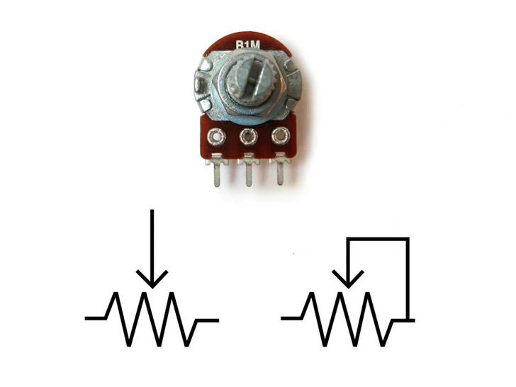
Potentiometers are measured in ohms, just like regular resistors. However, instead of color bands, their value is typically written directly on the component, such as "1M." You'll also see an "A" or "B" next to the value, which indicates the type of response curve it has.
Potentiometers with a "B" have a linear response curve, meaning the resistance increases evenly as you turn the knob (e.g., 10, 20, 30, 40, 50, etc.). On the other hand, potentiometers marked with an "A" have a logarithmic response curve, meaning the resistance increases more quickly (e.g., 1, 10, 100, 10,000, etc.).
Potentiometers have three terminals. These create a voltage divider, which is essentially two resistors connected in series. When two resistors are in series, the voltage between them will be somewhere between the power supply (e.g., 5V) and ground (0V).
For example, if you have two 10K resistors in series between a 5V power supply and ground, the point between them will be 2.5V because the resistors are equal in value. This middle point could be connected to the center pin of a potentiometer. When you turn the knob, the voltage at the center pin will either rise toward 5V or drop toward 0V, depending on which direction you turn it. This feature is useful for adjusting the intensity of a signal in a circuit—hence why potentiometers are often used as volume knobs.
This is often represented in circuits as a resistor with an arrow pointing toward its center.
If you only connect one of the outer pins and the center pin to the circuit, you’re just adjusting the resistance, not the voltage. This can be useful when you only need to control resistance at a specific point in the circuit without creating an adjustable voltage divider.
This setup is usually shown in a circuit as a resistor with an arrow pointing to one side, looping back to the center.