
Basic Electronics for Beginners in 20 Steps
Step 18: Your Second Circuit
Parts List:
- 2N3904 PNP transistor
- 2N3906 NPN transistor
- 47 ohm - 1/4 Watt resistor
- 1K ohm - 1/4 Watt resistor
- 470K ohm - 1/4 Watt resistor
- 10uF electrolytic capacitor
- 0.01uF ceramic disc capacitor
- 5mm red LED
- 3V AA battery holder
Optional:
- 10K ohm - 1/4 Watt resistor
- 1M potentiometer
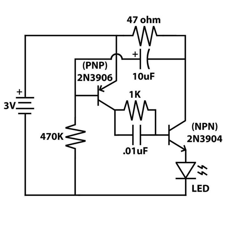
While this schematic might seem complicated, it’s actually quite simple. It uses components we’ve just covered to make an LED blink automatically.
Any general-purpose NPN or PNP transistors will work, but for this example, I’m using the 2N3904 (NPN) and 2N3906 (PNP). You can find the pin layouts for these transistors by looking up their datasheets. A good place for this is Octopart.com, where you can quickly find the part number and datasheet.
For example, the datasheet for the 2N3904 shows that pin 1 is the emitter, pin 2 is the base, and pin 3 is the collector.
Most of the other components, like resistors, capacitors, and the LED, are simple to wire up. However, there’s a tricky part in the schematic. Notice the curved line near the transistor. This line indicates that the capacitor jumps over the trace from the battery and connects to the base of the PNP transistor.
Also, keep in mind that electrolytic capacitors and LEDs are polarized, so they must be installed the correct way.
Once the circuit is built and powered on, it should blink. If it doesn’t, double-check your connections and component orientations.
A good troubleshooting trick is to count the components in the schematic and compare them to what’s on your breadboard. If the numbers don’t match, you missed something. Also, you can check the number of connections to each point in the circuit.
When it’s working, try changing the value of the 470K resistor. If you increase its value, the LED will blink slower, and if you decrease it, the LED will blink faster.
This resistor controls how fast the 10uF capacitor fills and discharges, which is directly linked to the blinking speed of the LED.
If you want more control over the blinking rate, replace the 470K resistor with a 1M potentiometer in series with a 10K resistor. Connect one side of the resistor to an outer pin on the potentiometer, and the other side to the base of the PNP transistor. The center pin of the potentiometer should connect to ground. Now, by turning the knob, you can change the blinking rate as you adjust the resistance.