
Basic Electronics for Beginners in 20 Steps
Step 19: Your Third Circuit
Parts List:
- 555 Timer IC
- 1K ohm - 1/4 Watt resistor
- 10K ohm - 1/4 Watt resistor
- 1M ohm - 1/4 Watt resistor
- 10uF electrolytic capacitor
- 0.01uF ceramic disc capacitor
- Small Speaker
- 9V battery connector
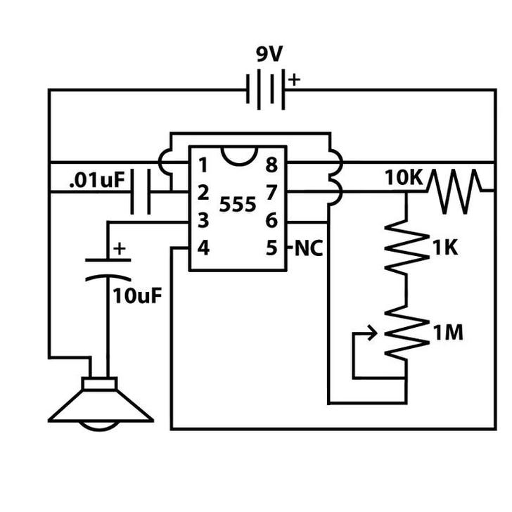
In this step, we’re using a 555 timer IC to generate sound through a speaker.
Here’s how it works: the way the components are set up around the 555 timer causes pin 3 to oscillate rapidly between high and low states. If you were to plot these fluctuations, you'd see a square wave—essentially a wave that alternates between two power levels. This rapid oscillation sends pulses to the speaker, causing it to vibrate at a high frequency. These vibrations move the air so quickly that we hear it as a continuous tone.
Ensure the 555 chip is positioned across the center of the breadboard, with no pins accidentally touching each other. After that, just follow the schematic to make the necessary connections.
Also, note the "NC" symbol in the schematic. This stands for "No Connect," meaning you don’t need to connect anything to that pin.
When choosing a speaker, opt for a small one, like the type found in greeting cards that play music. This circuit can’t power larger speakers, so the smaller, the better. Keep in mind that most speakers are polarized, so make sure the negative side is connected to ground (if needed).
If you want to enhance the setup, consider adding a volume control. You can do this by wiring one of the outer pins of a 100K potentiometer to pin 3, the middle pin to the speaker, and the other outer pin to ground.